You can draw various markups and annotations as well as create hyperlinks and calibration (measurement) on any page of the document using the tool-bar.
Screenshot displaying the tool-bar:
Each markup menu item on the tool-bar has associated sub-menu item.
Menu & Sub-Menu Icon Description:
Menu Icon Name |
Description |
Sub-Menu Icon Name |
Description |
|
This menu lets you select multiple portions in a single screen of a document |
|
Click to select multiple markups and annotations drawn on the document. After selection you can delete the multiple markups together. |
|
You can add a straight line, do freehand drawing and highlight area by selecting various options through this menu. |
|
Click to create a straight line on the document |
|
Click to draw freehand with a pen |
||
|
Click to draw an arrow |
||
|
You can highlight a portion of the document. The shape of the highlighted area will be rectangular |
||
|
You can create rectangular, ellipsoidal and cloud formed shapes and change shape attributes through this menu. The purpose is to point out any portions of the document for selection, highlighting etc. |
|
Click to draw a rectangular shape on the document |
|
Click to draw an ellipsoidal shape on the document |
||
|
Click to draw a cloud shape on the document |
||
|
You can add freeform texts, texts for notification purpose and callout text through this menu. |
|
Click to enter text on any portion of the document within a textbox |
|
Click to enter note on any portion of the document to appear as a pop-up. |
||
|
Click to create a call-out |
||
|
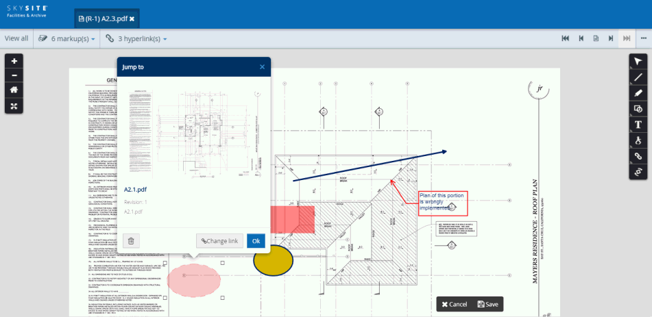
You can insert a hyperlink through this menu to point to another file or point to a different screen of the same file. The hyperlinked areas can be of varied shapes and sizes. |
|
Add a hyperlink to link to another or other portions of same document. The hyperlinked area shape is cloud. |
|
Add a hyperlink to link to another or other portions of same document. The hyperlinked area shape is ellipse. |
||
|
Add a hyperlink to link to another or other portions of same document. The hyperlinked area shape is rectangle. |
||
|
You can draw a calibration line and based on that line the application will measure the length and area of various shapes and lines called measurement annotation. You need to draw these annotations after drawing the calibration line. |
||
|
You can rotate a document by 90 degrees up to 360 degrees using this feature. |
||
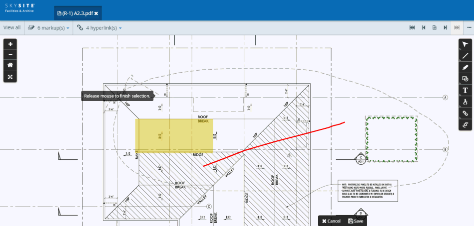
You can use the multi-select markup feature to select multiple markups/annotations drawn on the document and then delete those markups together..
Select the multi-selection icon from the tool-bar and then move the mouse pointer over the drawn markups/annotations. After this is done, release the mouse pointer to select the markups together
Screenshot below displays multiple markups selected using the multi-selection markup:
After you release the mouse pointer, click on any one of the selected markups.
A pop-up box asking you to delete the selected markups open up. This is shown below,
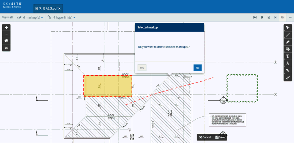
Click [Yes] to delete the selected markups.
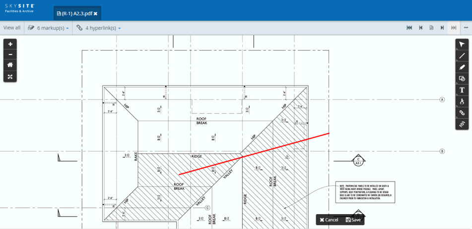
Below is given a full description of drawing & saving a particular markup (example of 'Line markup' is taken)
Click on the Line menu and then click on the Line markup icon from the tool-bar
Now, click and drag to draw a line
A fully drawn line markup is shown in the screenshot below,
Click on the line markup to open the settings of the markup. This is shown below,
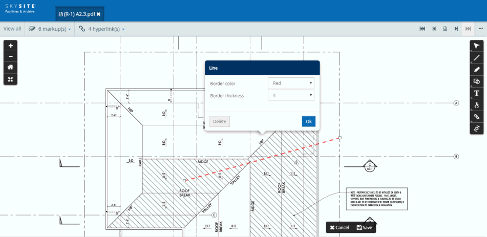
Drawing details:
Border Color: Click the Border Color drop-down to change the color of the line markup. The colors are pre-defined in the application. The colors which can be selected from the drop-down are Red, Blue, Green, Yellow, Black & White.
Border Thickness: Click the Border Thickness drop-down to change the size or thickness of the line. For example, the line thickness can be 1, 2, 4, 6, 8 & 16. The thickness measures are pre-defined in the application.
Delete button: Click on [Delete] button to remove the drawn line.
OK button: Click on [OK] button to keep the drawn line on the document after making changes in color or thickness (is necessary).
Other operations:
After you click on the line markup, small white-boxes appear on the two end points of the line. Stretch the end points to increase or decrease the line length, or drag any one of the end points to rotate the line around.
Click on the line to select it, then move the Line by dragging the mouse pointer and then release the same at any position on the document.
Note: The operation of stretching of the end points [small white boxes at the end of markups], changing the mark-up shape direction on a single plane and also moving the markups can be achieved on all different types of markups and annotation.
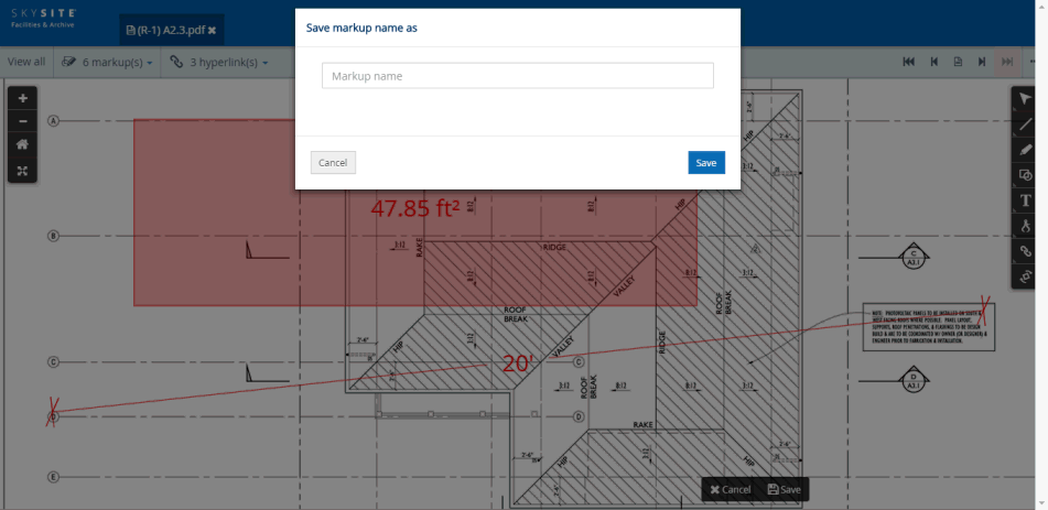
After you draw the line markup, click on the [Save] button [highlighted with red rectangle in screenshot below] at the bottom right-hand corner of the screen to save the markup. The Save markup name as pop-up box appears. This is shown below,
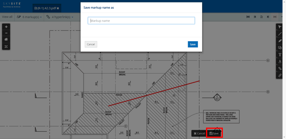
Enter the name of the line markup on this pop-up box and click [Save] button to save the markup
Note: Uncheck the checkbox to make the markup private meaning that it will only be visible to the user who created the markup and not to other users of the account.
After you save the markup it will appear under the 'Saved markup(s)' drop-down present on the top of the Viewer.
Click the 'Saved markup(s)' drop-down [highlighted with red rectangle on the screenshot below] to view all the saved markups drawn & saved previously on the document.
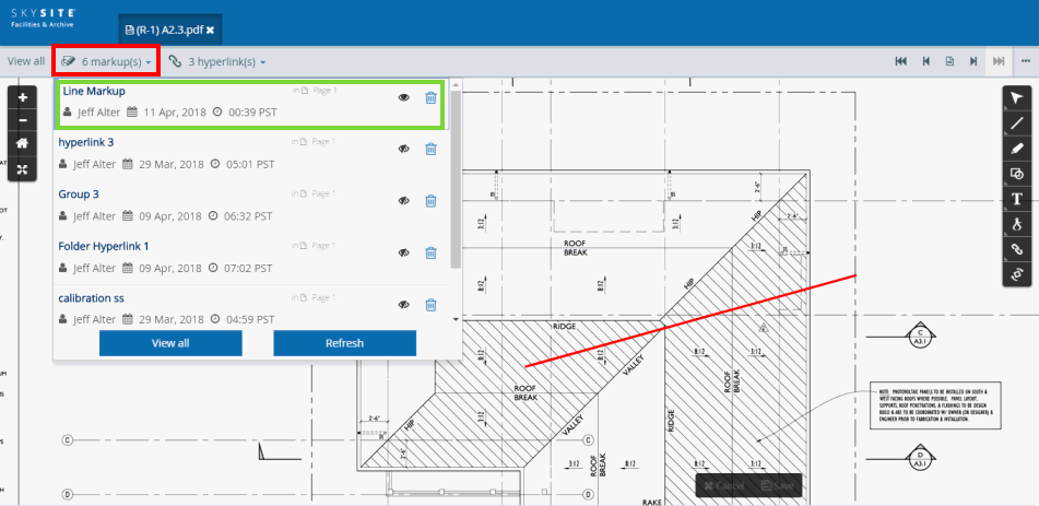
Now, click on the recently drawn & saved markup row [highlighted with green rectangle on the screenshot above] to make the markup annotation shape appear & disappear on the document
Note:
This icon  [Toggle
markup view ON/OFF] means that the markup shape is visible
on the Viewer and this icon
[Toggle
markup view ON/OFF] means that the markup shape is visible
on the Viewer and this icon  means that the markup
shape is hidden from view. You can click on the saved annotation row to
make the markup shape appear and disappear.
means that the markup
shape is hidden from view. You can click on the saved annotation row to
make the markup shape appear and disappear.
Click  [Delete]
button to delete the saved markup.
[Delete]
button to delete the saved markup.
Note: After the markup is saved you cannot change the color, thickness, stretch the lines or move the line or for that matter do anything on the markup except make the markup appear & disappear from the Viewer screen. You can only delete the saved markup from the 'Saved markup(s)' drop-down.
Other markups/annotations are drawn & saved in the Viewer in a similar manner as the 'Line markup'.
Brief description of each of these markups are given below,
This menu provides the user with the option to draw a straight line, do freehand drawing and highlight any intended area.
Note: The 'Line markup' from this menu has already been described.
Click on the Line menu and then click on the Freehand markup icon from the tool-bar
Now, click and drag across the document to draw the Freehand
A fully drawn freehand markup is shown in the screenshot below,
Click on the line markup to open the settings of the markup. This is shown below,
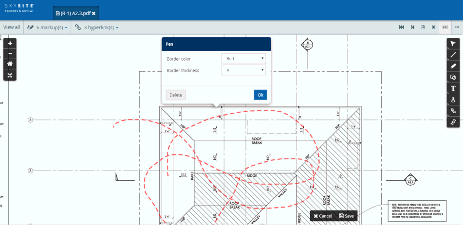
Drawing details:
Border Color: Click the Border Color drop-down to change the color of the freehand markup. The colors are pre-defined in the application. The colors which can be selected from the drop-down are Red, Blue, Green, Yellow, Black & White.
Border Thickness: Click the Border Thickness drop-down to change the size or thickness of the freehand line. For example, the line thickness can be 1, 2, 4, 6, 8 & 16. The thickness measures are pre-defined in the application.
Delete button: Click on [Delete] button to remove the drawn freehand line.
OK button: Click on [OK] button to keep the drawn freehand line on the document after making changes in color or thickness (is necessary).
You can only move the freehand markup from its position on the document.
Note: The saving process is not explained separately for this markup as it is similar to that of 'Line markup'.
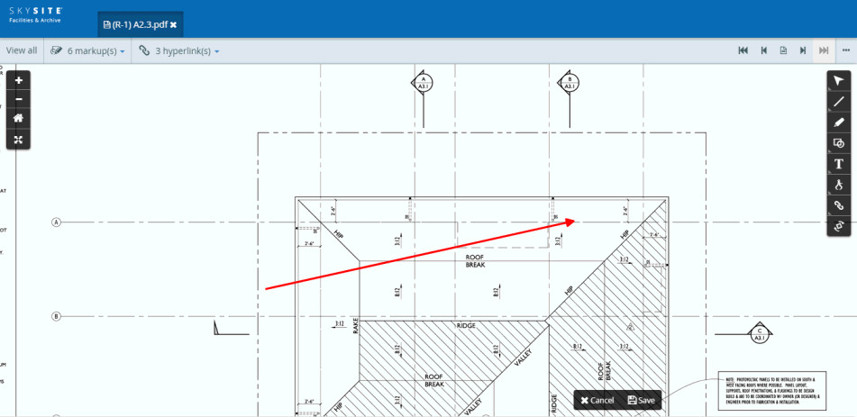
Click the ‘Line’ icon on the tool-bar menu.
The ‘Line’ menu will appear.
Click the ‘Arrow’ icon on the 'Line markup' menu to draw the arrow
Now, single-click on the portion of the document from where you would like to start the arrow, hold & drag the mouse pointer and then release the pointer to end the arrow (the arrow head will point to the portion of the document where you had released the mouse pointer)
A fully drawn arrow will now be visible.
Screenshot below displays a fully drawn arrow:
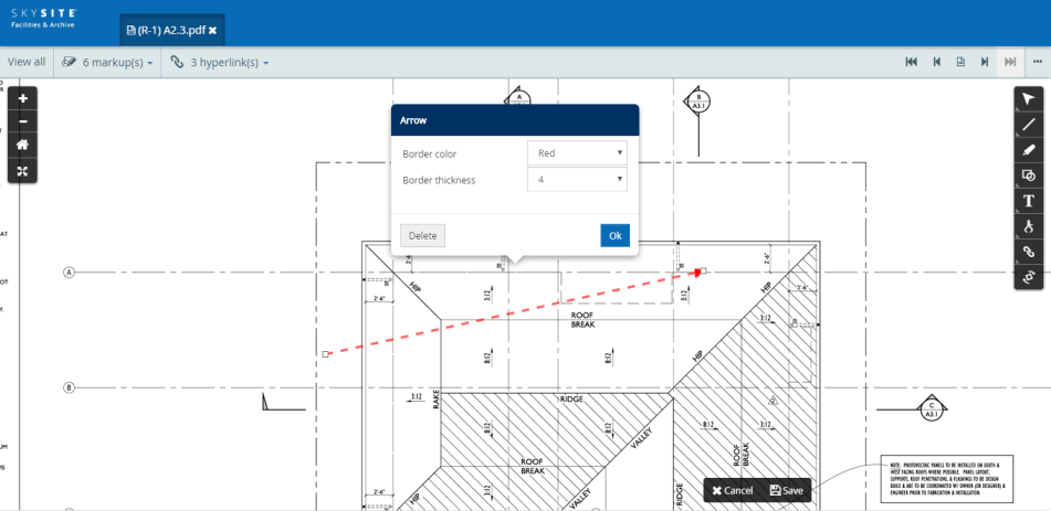
Click on the arrow to select it and view the arrow settings
Screenshot below displays a selected arrow with ‘Settings’ pop-up box:
If you like to change the position of the arrow, then single-click on the arrow, hold the mouse pointer and drag the arrow around and then release the mouse pointer at a position of the document where you would like to place the arrow.
Also, you can stretch & contract the end points of an arrow to change its length and position
Settings:
Border color: You can change the color of the arrow from this drop-down. The colors to be chosen from are red, blue, green, yellow, black or white. Default color is red.
Border thickness: You can change the thickness of the arrow from this drop-down. The minimum thickness is 1 and the maximum is 16. Default thickness is 4.
Click [Delete] button to remove the drawn arrow
Click [Ok] button to close the settings drop-down after making any necessary changes.
Note: The saving process is not explained separately for this markup as it is similar to that of 'Line markup'.
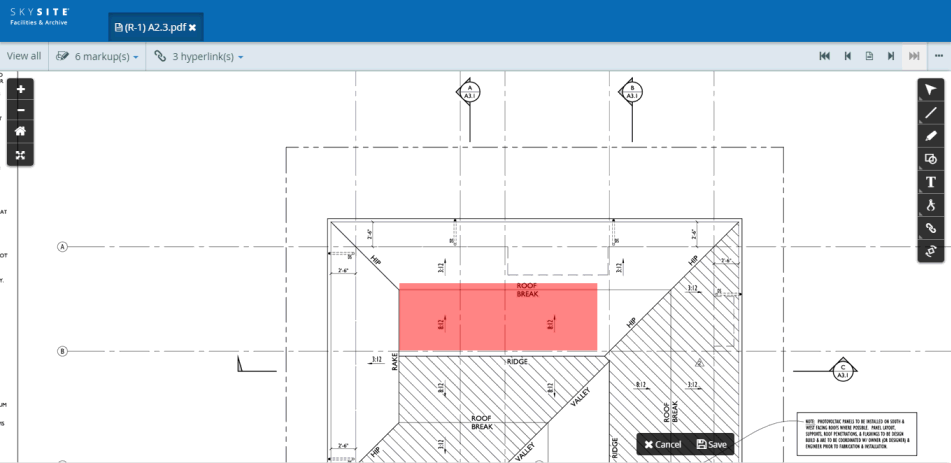
Click on the rectangular highlight menu from the tool-bar
Now, click and drag across the document to draw the rectangular highlight markup
A fully drawn rectangular highlight markup is shown in the screenshot below,
Click on the line markup to open the settings of the markup. This is shown below,
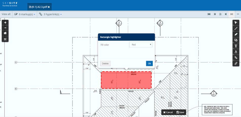
Drawing details:
Fill Color: Click the Fill Color drop-down to change the color of the freehand markup. The colors are pre-defined in the application. The colors which can be selected from the drop-down are Red, Blue, Green, Yellow, Black & White.
Delete button: Click on [Delete] button to remove the drawn freehand line.
OK button: Click on [OK] button to keep the drawn freehand line on the document after making changes in color or thickness (is necessary).
The highlighted area is translucent as you can view any writing or image on the document, falling under the highlighted area. The four end points (identified by the white rectangular dots) around the textbox can be dragged outward or inward to increase or decrease the area of the textbox.
Note: The saving process is not explained separately for this markup as it is similar to that of 'Line markup'.
This menu is used to create shape markups on the document. The user has the option to choose any one of the rectangle, ellipse and cloud mark-up. Options to fill the annotation area with various colors, change the border width and color out of any of the 3 shapes is also provided.
Click on the Shape menu and then click on the rectangle markup icon from the tool-bar
Now, click and drag across the document to draw the rectangular markup
Click on a drawn rectangle to open the 'Settings' pop-up of the rectangular markup
The screenshot below displays a drawn rectangle and another one whose 'Settings' pop-up is open,
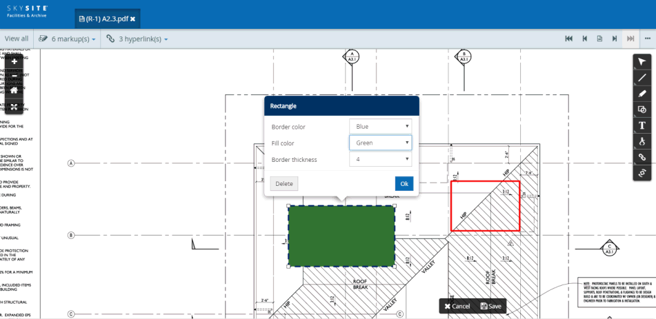
The rectangle area can be increased or decreased and the size of the rectangle increased or decreased by dragging the corner points of the rectangle outward or inward. Also, the rectangular area can be mirrored in the opposite direction on a single plane by dragging any one of the rectangle corners. For example, if you stretch the upper left-hand corner of the rectangle then all the other corners will also get stretched except for the lower right-hand corner of the rectangle.
Drawing Details:
Border Color: Click the this drop-down to change the color of the rectangle border or to make it transparent. The colors are pre-defined in the application. The colors which can be selected from the drop-down are Red, Blue, Green, Yellow, Black & White.
Border Thickness: Click this drop-down to change the border thickness of the rectangular shape. For example, the line thickness can be 1, 2, 4, 6, 8 & 16. The thickness measures are pre-defined in the application.
Fill Color: Click the this drop-down to fill the rectangle with a selected color or to make the area covered by the rectangle transparent. The colors are pre-defined in the application. The colors which can be selected from the drop-down are Red, Blue, Green, Yellow, Black & White.
Delete button: Click on [Delete] button to remove the drawn rectangle.
OK button: Click on [OK] button to keep the drawn rectangle on the document.
Note: The saving process is not explained separately for this markup as it is similar to that of 'Line markup'.
Click on the Shape menu and then click on the ellipse markup icon from the tool-bar
Now, click and drag across the document to draw the ellipse markup
Click on a drawn ellipse to open the 'Settings' pop-up of the ellipse markup
The screenshot above displays a drawn ellipse and another one whose 'Settings' pop-up is open,
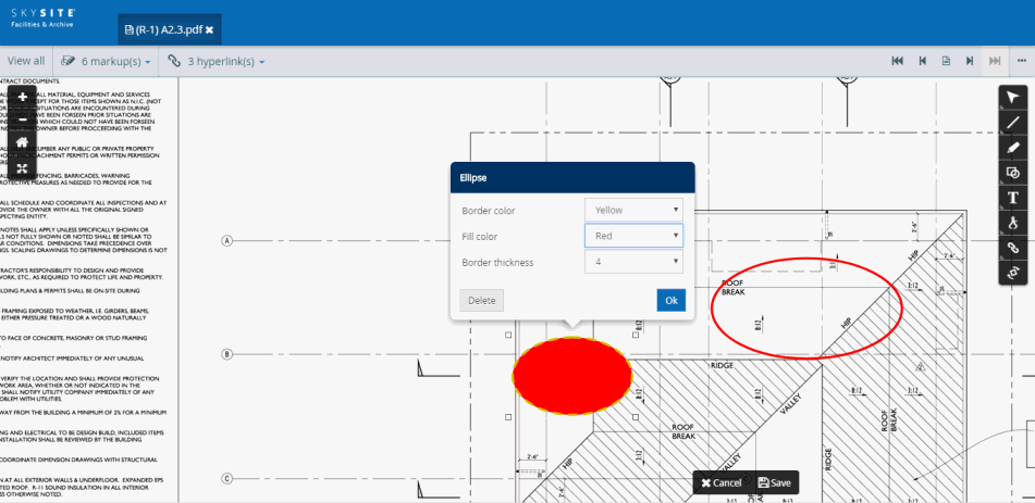
The ellipse area can be increased or decreased and the size of the ellipse increased or decreased by dragging the corner points of the ellipse (marked by the white rectangular dots) outward or inward. The ellipse can also be moved around like the rectangle.
Drawing Details:
Border Color: Click the this drop-down to change the color of the ellipse border or to make it transparent. The colors are pre-defined in the application. The colors which can be selected from the drop-down are Red, Blue, Green, Yellow, Black & White.
Border Thickness: Click this drop-down to change the border thickness of the ellipsoidal shape. For example, the line thickness can be 1, 2, 4, 6, 8 & 16. The thickness measures are pre-defined in the application.
Fill Color: Click the this drop-down to fill the rectangle with a selected color or to make the area covered by the ellipse, transparent. The colors are pre-defined in the application. The colors which can be selected from the drop-down are Red, Blue, Green, Yellow, Black & White.
Delete button: Click on [Delete] button to remove the drawn ellipse.
OK button: Click on [OK] button to keep the drawn ellipse on the document.
Note: The saving process is not explained separately for this markup as it is similar to that of 'Line markup'.
Click on the Shape menu and then click on the cloud markup icon from the tool-bar
Now, click and drag across the document to draw the cloud markup
Click on a drawn cloud to open the 'Settings' pop-up of the cloud markup
The screenshot below displays a drawn cloud and another one whose 'Settings' pop-up is open,
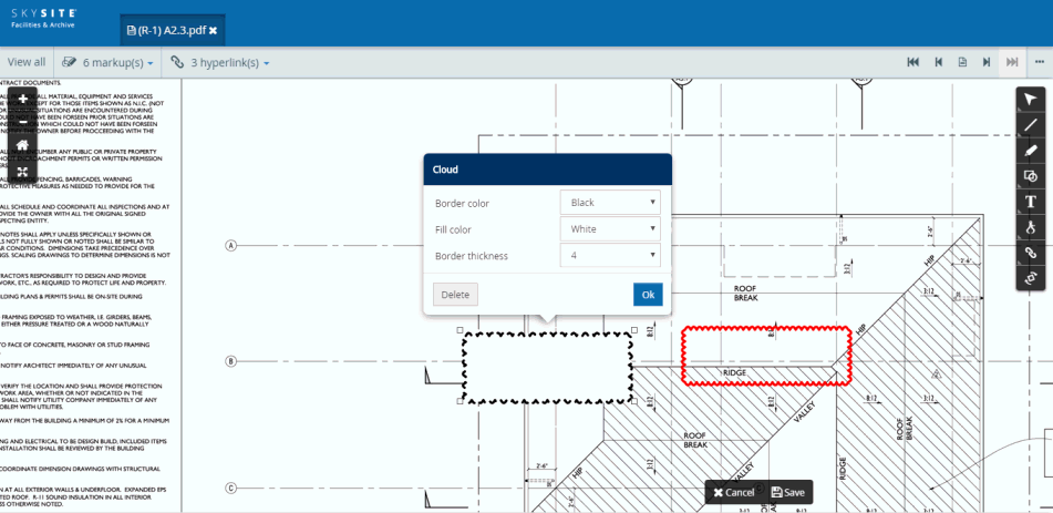
The cloud area can be increased or decreased and the size of the cloud increased or decreased by dragging the corner points of the cloud (marked by the white rectangular dots) outward or inward. Also, the cloud area can be mirrored in the opposite direction on a single plane by dragging any one of the rectangle corners. For example, if you stretch the upper left-hand corner of the cloud then all the other corners will also get stretched except for the lower right-hand corner of the cloud.
Drawing Details:
Border Color: Click the this drop-down to change the color of the cloud border or to make it transparent. The colors are pre-defined in the application. The colors which can be selected from the drop-down are Red, Blue, Green, Yellow, Black & White.
Border Thickness: Click this drop-down to change the border thickness of the cloud shape. For example, the line thickness can be 1, 2, 4, 6, 8 & 16. The thickness measures are pre-defined in the application.
Fill Color: Click the this drop-down to fill the rectangle with a selected color or to make the area covered by the cloud, transparent. The colors are pre-defined in the application. The colors which can be selected from the drop-down are Red, Blue, Green, Yellow, Black & White.
Delete button: Click on [Delete] button to remove the drawn cloud.
OK button: Click on [OK] button to keep the drawn cloud on the document.
Note: The saving process is not explained separately for this markup as it is similar to that of 'Line markup'.
This menu lets you insert textual information on the file either directly visible on a textbox or present inside a note pop-up (created for the purpose of avoiding direct visibility) or populated inside a callout.
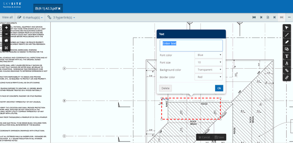
Click on the Text menu and then click on the text markup icon from the tool-bar
Now, click and drag across the document to draw the textbox markup. As soon as you draw the textbox markup the 'Settings' pop-up appears.
Screenshot below displays a drawn textbox markup whose 'Settings' pop-up is open,
The four end points (identified by the white rectangular dots) around the textbox can be dragged outward or inward to change the shape and area of the textbox.
The Text Settings pop-up box appears automatically once you draw the textbox.
Enter the text in the space provided in the 'Settings' pop-up box. As soon as you enter text, the text gets automatically & simultaneously added inside the drawn textbox
Screenshot below displays a textbox after text entry is completed:
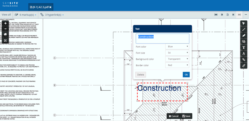
Drawing Details:
Font Color: Click this drop-down to change the font color of the selected text. The font colors are pre-defined in the application. The colors which can be selected from the drop-down are Red, Blue, Green, Yellow, Black & White.
Font Size: Click this drop-down to change the font size of the text, after selecting the text. The font sizes are pre-defined in the application. The smallest font size that can be selected is 8 and the largest is 72.
Background Color: Click this drop-down to change the color of the textbox area within which the text is written or to make the textbox transparent. The background colors are pre-defined in the application. The colors which can be selected from the drop-down are Red, Blue, Green, Yellow, Black & White.
Border Color: Click this drop-down to change the color of the textbox border or to make it transparent (i.e. removing the border of the textbox). The colors are pre-defined in the application. The colors which can be selected from the drop-down are Red, Blue, Green, Yellow, Black & White.
Delete button: Click on [Delete] button to remove the drawn textbox.
OK button: Click on [OK] button to keep the drawn textbox on the document and close the 'Settings' pop-up box.
Note: The saving process is not explained separately for this markup as it is similar to that of 'Line markup'.
Click on the Text menu and then click on the note markup icon from the tool-bar
Now, click on the document to draw the note markup. As soon as you draw the note markup the 'text entry' pop-up appears.
Screenshot below displays a drawn note markup whose 'Text entry' pop-up appears as shown below,
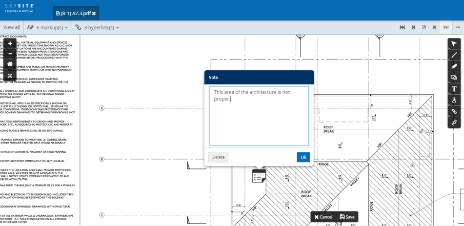
Drawing Details:
Text entry section: Enter relevant text to be included within the 'Note' area.
Delete button: Click on [Delete] button to remove the drawn note.
OK button: Click on [OK] button to keep the drawn note entry area on the document and close the text entry area.
Click the Note icon present on the document to view the text.
Note: The saving process is not explained separately for this markup as it is similar to that of 'Line markup'.
Click the ‘Text’ icon on the tool-bar menu
The ‘Text’ mark-up sub-menu will appear.
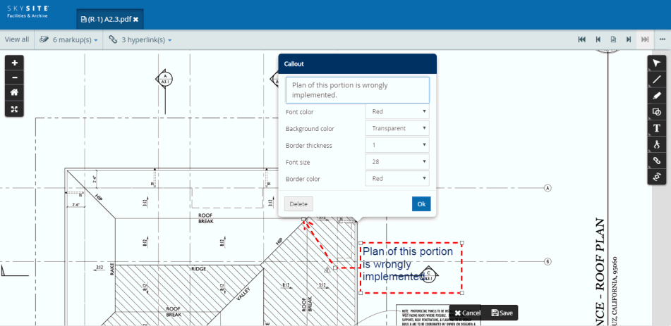
Click the ‘Callout’ icon on the Text menu to draw the callout
After clicking the ‘Callout’ icon, click on that point of the document from where the arrow head will start (i.e. the position which the arrow head points to), drag the mouse pointer to draw the callout and then after the drawing completes release the mouse pointer to complete the drawing.
As soon as you complete the drawing, the 'Settings' pop-up menu appears on the callout
Screenshot displaying a newly drawn callout with the 'Settings' pop-up menu:
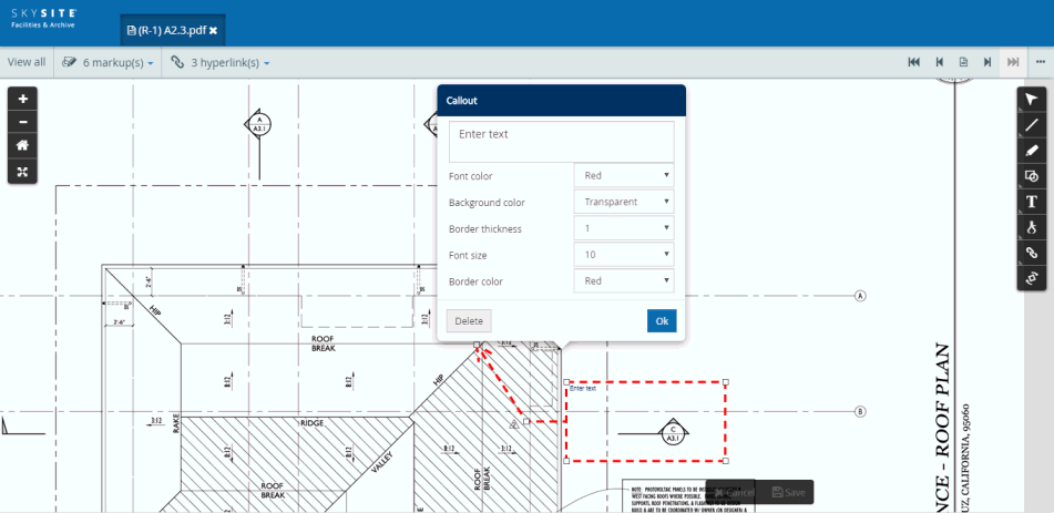
The Callout structure consists of an arrow which points to a piece of text, a symbol or an illustration on the document. The arrow is connected to a rectangle text box within which information regarding that point, to which the arrow points, is entered.
The Callout Structure Diagrammatic representation:
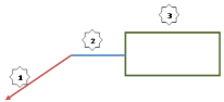
Arrow: The Arrow is the first part of the callout structure. It points to the portion of the document for which information is entered within the rectangular textbox.
Connector: The Connector facilitates in the connection between the arrow and the rectangular textbox.
Rectangular Textbox: The rectangular textbox consists of the information regarding the point at the tip of the arrow.
Note:
These three components of the callout structure will not overlap with each other.
The Arrow & the Connector will have a minimum length beyond which these two component length cannot be reduced. Hence, for best viewing experience a minimum limit on callout arm size has been kept according to current zoom level of document.
Immediately, after the callout structure is drawn, the Callout Settings pop-up box appears. On this pop-up box, you can enter information to be viewable inside the rectangular structure. You can enter text within the pop-up box and these will be automatically visible inside the rectangular textbox.
Screenshot displaying entered text on the callout settings pop-up which gets automatically updated inside the rectangular structure of the callout:
Settings:
Font color: You can change the font color of the text entered in the rectangular section of the callout. The font color can be red, blue, green, yellow, black or white. Default color is blue.
Fill color: You can change the fill color of the rectangular section of the callout. The font color can be red, blue, green, yellow, black, white or no color i.e. transparent. Default is no color which is transparent.
Border thickness: You can change the thickness of the callout border or outline from this drop-down. The minimum thickness is 1 and the maximum is 16. Default thickness is 4.
Font size: You can change the font size of the text entered in the rectangular section of the callout. The minimum font size is 8 and the maximum is 72. Default font size is 10.
Border color: You can change the color of the callout border or outline from this drop-down. The border colors can be red, blue, green, yellow, black or white. Default color is red.
Click [Delete] button to remove the drawn callout
Click [Ok] button to close the settings drop-down after making any necessary changes.
If by any chance, the size of the text entered exceeds the area of the drawn callout but you click [Ok] button then a message saying “Text entry denied. Reduce size, curtail text or expand area to proceed”.
This means you can reduce the text size, restrict the volume of text entered or expand the size of the callout rectangular area.
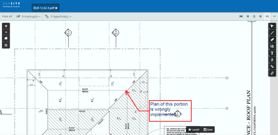
After you click the [Ok] button a fully drawn callout becomes visible.
Screenshot below displays a fully drawn callout:
The Callout structure, both rectangular as well as the arrow portion can be stretched & moved around. The structure shape and arrow length can be changed by moving the white dot, present at the four corners of the rectangle, the connecting point between the rectangle & the arrow as well at the end of the arrow.
The following actions can be performed with the callout structure:
The rectangular box size can be increased or decreased by dragging any of the white dots at any one end of the rectangle outward & inward, respectively.
The white dot present at the end of the arrow can be moved around so that the arrow start point can be changed to the mid-point of any of the four sides of the rectangular box. Also, this dot can be moved outward or inward to increase or decrease the arrow length
The connecting white dot between the rectangular box & the arrow can be moved outward or inward, thereby changing the shape of the arrow. Also, this dot moves along with the white dot present at the end of the arrow.
Tapping & then dragging the rectangular box outward or inward will increase or decrease the arrow length, respectively. Also, the rectangular box can be rotated around the end-point of the arrow.
The arrow head will point to the same position on the document when the textbox is move around. For panning users will have to click inside the rectangular text area/textbox and not anywhere within the extended selected area. It may happen that the callout arrow may point to a position which happens to fall within the rectangular textbox area of the callout structure. In this case, for enhanced viewing experience, the callout structure may adjust itself; due to which the callout text box may displace itself out of the purview of the arrow head, however the arrow will be pointing to same position as before.
Note: The saving process is not explained separately for this markup as it is similar to that of 'Line markup'.
Please refer to Rotating document pages help file for details.
Calibration tool allows the user to create a new calibration line and then based on the length of that calibration line application calculates the length and area of various lines and shapes.
The calibration tool will be used for measuring:
The length of a line drawn on the document
he area covered by a rectangular shape
The area covered by an ellipsoidal shape
The length of a line drawn in freehand mode
The area covered by a curve drawn in freehand mode
User first draws a calibration line and enters the length of the line. In reference to the length of the calibration line, application automatically calculates the length and area of various lines and shapes. User must first draw the Calibration line first for the application to calculate the subsequent lengths & areas.
The Calibration line (Calibration Line) must be drawn first on the document and then the length of the line must be set by the user. Based on the entered length of this Calibration line, the length or area of other lines and shapes will be calculated by the application.
The user first will have to open any PDF document in
the SKYSITE F&A Viewer.
An opened-up document in the Viewer is shown below, 
User will have to click the [Calibration] icon and then click on the [Calibration ruler] icon [highlighted by red rectangle in the screenshot above] on the tool-bar. After clicking the Calibration ruler icon, the user will click on any point in the document and then drag and release the mouse click to draw the calibration ruler. As soon as user draws the calibration ruler line, a pop-up box appears where user will have to select the measurement unit (either in imperial units which is feet and inches or in metric unit which is meters and centimeters).
A newly drawn Calibration line on the document is displayed below,
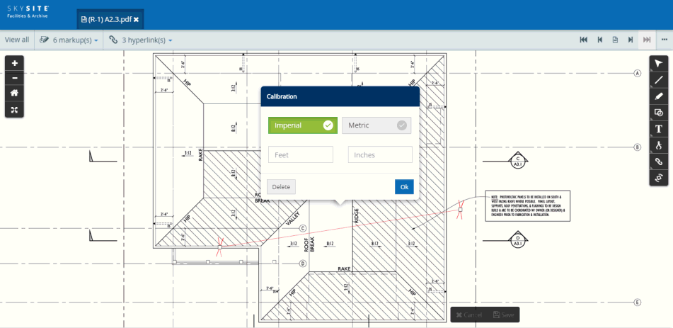
After selecting the measurement unit user will have to enter the length of the line. For example, user selects the ‘Imperial’ unit of measurement, hence will have to enter the length of the line in feet & inches.
Screenshot below
displays the length entered and the Unit of Measurement selected:
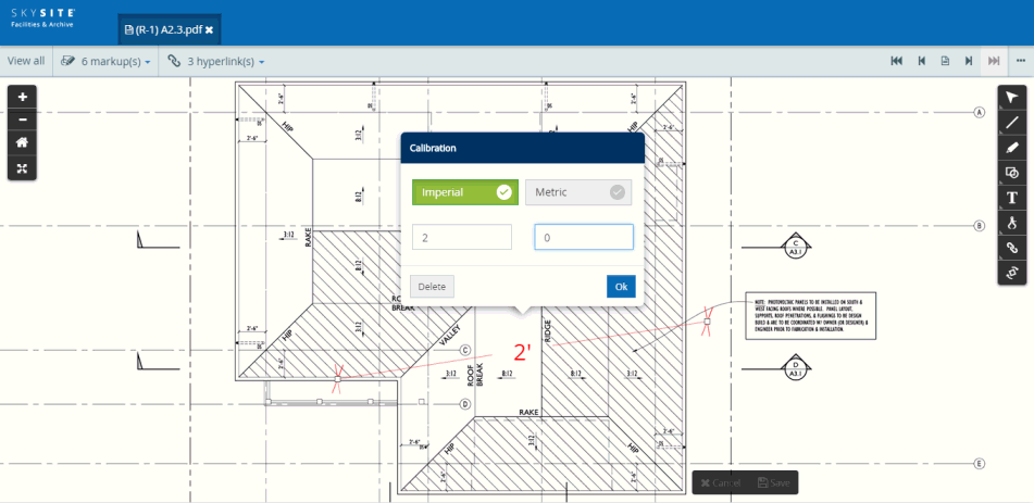
Note: The Length textbox only accepts numerical values.
After entering the length measure and selecting the unit of measure the user needs to click on the [Ok] button at the bottom right-hand corner of the Calibration pop-up box.
User can click on [Delete] button to remove the Calibration line. In case of a scenario, when user has already drawn one or more measurement annotations with respect to an existing Calibration line, then once the Calibration line is deleted, all the measurement values associated with the Measurement annotations will turn to zero.
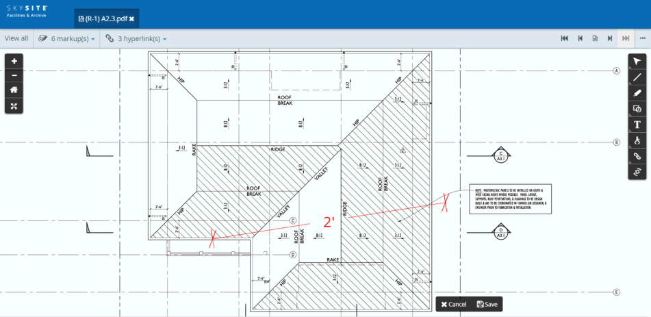
Screenshot below displays a fully drawn Calibration line:
Note: The calibration line can be stretched outward, dragged inward or rotated around by clicking, selecting and then dragging either one of the two white dots (at each end of the line) across the document. These white Dots are present at both ends of the Calibration line. The calibration line dragged outward or inward, but the calibrated length entered by the user on the Calibration line will remain the same until & unless the user recalibrates the length of the line from the calibrator pop-up box. Also, when the Calibration line is dragged outward or inward, all the measurement values associated with measurement lines and shapes will get updated simultaneously.
After you draw the Calibration line, the measurement line and area drawing annotation icons in the tool-bar will appear activated, while the calibration annotation icon will appear disabled (because it has already been drawn). This is shown below,
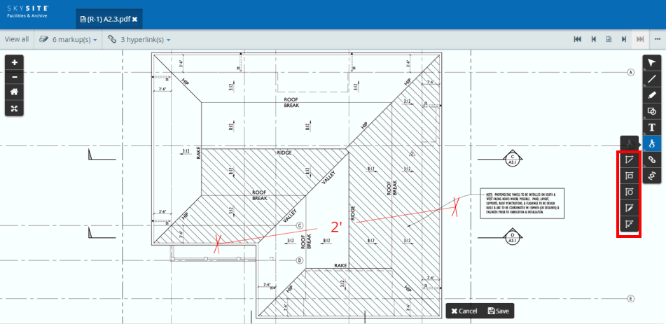
Measurement lines and areas can only be drawn (along with the setting of the length as well as the unit of measurement) after the Calibration line has been drawn.
The length of a line will be automatically calculated
by the application with respect to the length of the Calibration line.
This line can be drawn by clicking the Line
Measurement Tool icon  and then dragging across
the document. The length of the line will be automatically calculated
by the application considering the length of the Calibration line. Also,
the unit of measurement of the length of the Measurement
Line will be similar to that of the Calibration line. After drawing
the measurement line, user can click on the line to view the settings
of the line.
and then dragging across
the document. The length of the line will be automatically calculated
by the application considering the length of the Calibration line. Also,
the unit of measurement of the length of the Measurement
Line will be similar to that of the Calibration line. After drawing
the measurement line, user can click on the line to view the settings
of the line.
Screenshot below displays the newly drawn line and its length (along with Settings):
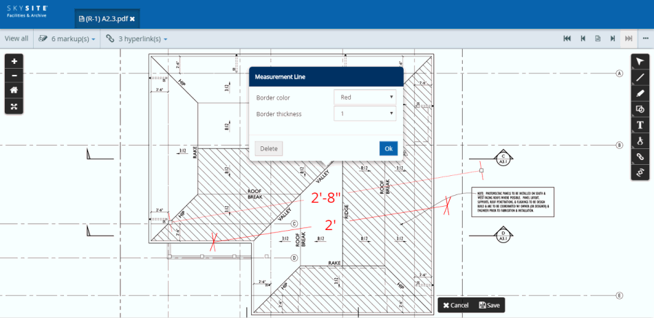
The newly drawn line will have Settings section from where the user can change the color & the thickness of the line.
The application will provide dynamic display of the length of the Measurement Line. This means that as & when the line is stretched outward or stretched inward, the displayed length will adjust itself automatically and will increase or decrease accordingly.
Example: If a Calibration line length has been set at say, 20 inches then the Measurement Line of a similar length (drawn at any angle) will have a displayed length of 20 inch. Now, say the Measurement Line is stretched in such a way, so that its length is doubled. In this case, the displayed length will be 40 inches. Also, as the displayed length of the Measurement Line is dynamic, when user stretches the line, the user will be able to view the change in the displayed length when the line is in the process of being stretched outward.
Also, if the Calibration line is stretched outward or inward, the length of the Calibration line will not change (unless user changes it from Calibration pop-up box) but the length of the measurement line will change.
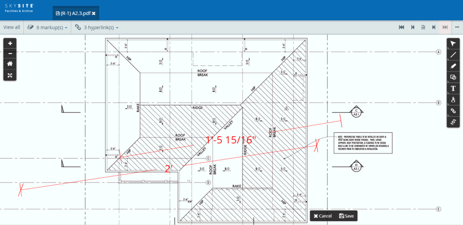
Screenshot below displays the length of the measurement line calculated based on the length of the Calibration line (2 feet):
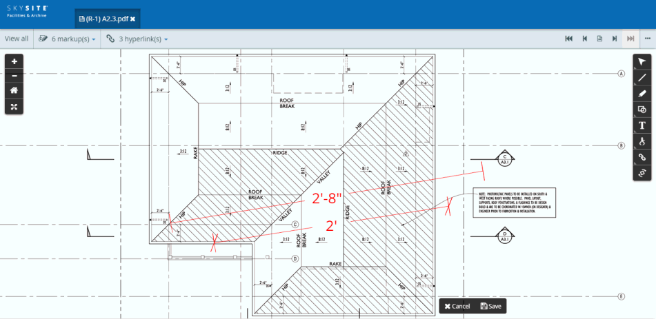
The Calibration line is now stretched outward, but user has not changed the length of the Calibration line which remains 2 feet. Hence, the application changes the length of the measurement line accordingly. If the length of the calibration line is increased by stretching the line outward then the length of the measurement line will decrease but if the length of the calibration line is decreased by shrinking the line inward then the length of the measurement line will increase.
Screenshot below displays the length of the measurement line calculated based on the length of the Calibration line stretched outward but the user populated length is kept at 2 feet:
The area of a rectangle will be automatically calculated
by the application with respect to the length of the Calibration line.
The rectangle can be drawn by clicking the Rectangle Measurement Tool
icon  and then dragging across
the document. The calculated
area will be displayed in the middle of the rectangle. Also, the unit
of measurement of the area will be similar to that of the Calibration
line.
and then dragging across
the document. The calculated
area will be displayed in the middle of the rectangle. Also, the unit
of measurement of the area will be similar to that of the Calibration
line.
Screenshot
below displays the newly drawn rectangle and its area (with settings):
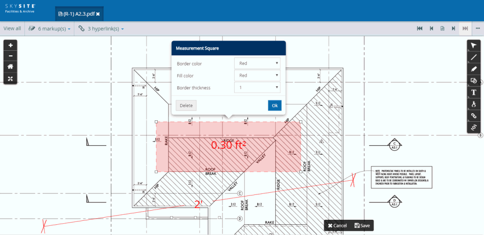
The newly drawn rectangle will have Settings section from where the user can change the color of the outline border of the rectangle, fill the rectangular area with a color and increase or decrease the thickness of the rectangle border.
The application will provide dynamic display of the area of the Measurement Rectangle. This means that as & when the line is stretched outward or reduced inward, the displayed length will adjust itself automatically and will increase or decrease accordingly.
The area of a circle (ellipse) will be automatically
calculated by the application with respect to the length of the calibration
line. The circle can be drawn by clicking the Circular
Measurement Tool icon  and then dragging
across the document.
and then dragging
across the document.
The application calculates the area falling within the elliptical shape. This calculated area will be displayed in the middle of the circle (ellipse). Also, the unit of measurement of the area will be similar to that of the Calibration line.
Screenshot below displays the newly drawn circle (ellipse) and its area (with settings):
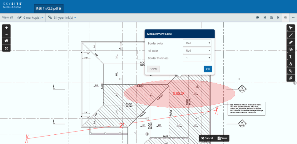
The newly drawn circle or ellipse will have Settings section from where the user can change the color of the outline border of the circle (ellipse), fill the ellipsoidal area with a color and increase or decrease the thickness of the circle (ellipse) border.
The application will provide dynamic display of the area of the Measurement Circle. This means that as & when the circle or ellipse is stretched outward or shrinked inward, the displayed area will adjust itself automatically and will increase or decrease accordingly.
As can be seen from the above screenshot, the ellipsoidal area can be stretched outward or inward by dragging any one of the 8 blue dots present on the four corners and each mid-point of the four sides of the circle (ellipse).
The length of an arbitrary line or curve drawn in freehand
form will be automatically calculated by the application with respect
to the length of the Calibration line. This curve can be drawn by clicking
the Freehand Length Measurement
Tool icon  and
then moving fingers across the document. The length of the curve will
be automatically calculated by the application considering the length
of the Calibration line. Also, the unit of Measurement of the length of
the Measurement Freehand Line
will be similar to that of the Calibration line.
and
then moving fingers across the document. The length of the curve will
be automatically calculated by the application considering the length
of the Calibration line. Also, the unit of Measurement of the length of
the Measurement Freehand Line
will be similar to that of the Calibration line.
Screenshot below displays the newly drawn freehand line (curve) and its length (with settings):
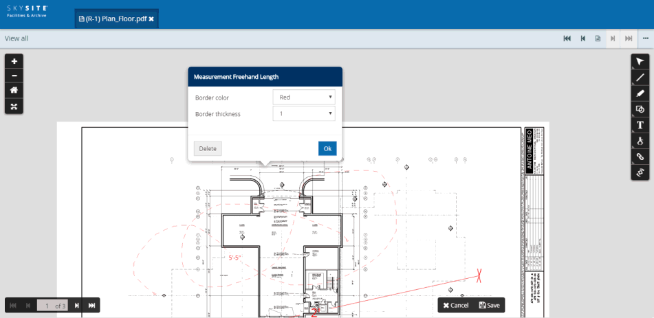
The newly drawn freehand line (curve) will have Settings section from where the user can change the color & the thickness of the line (curve).
The application will provide dynamic display of the length of the measurement freehand line. This means that as & when the freehand line (curve) is drawn outward or inward or drawn around the document, the displayed length will adjust itself automatically and will increase or decrease accordingly.
The Freehand Area can be drawn by clicking the Freehand
Area Measurement Tool icon  and then dragging across the
document.
and then dragging across the
document.
Example of a drawn Freehand Area:
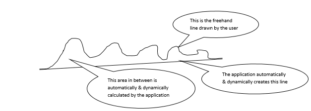
Procedure for calculating the area of the Freehand Area:
The user can draw any line haphazardly on the document, but the two end points will be connected by a straight line created by the application automatically. This straight line will increase automatically as & when the user draws the freehand line. The area falling within the two lines will also be automatically calculated by the application. Hence, the curve drawn will be automatically closed between the start point and the end point. The area changes automatically and simultaneously with the drawing of the freehand line by the user and the auto creation of the straight line by the application with respect to the freehand line length. This calculated area will be displayed in the middle of the freehand area. Also, the unit of Measurement of the area will be similar to that of the Calibration line.
Screenshot
below displays the newly drawn measurement freehand area and its calculated
area (with settings): 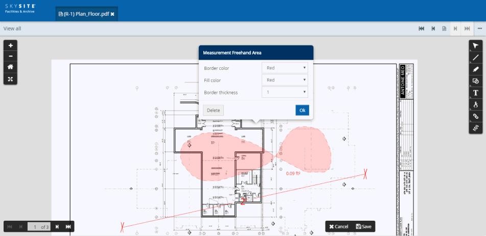
The newly drawn Measurement Freehand Area will have Settings from where the user can change the color of the outline border of the freehand area, fill the area with a color and increase or decrease the thickness of the freehand area border.
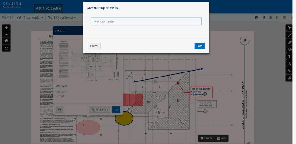
After drawing any of the measurement lengths or areas and performing all the relevant operations on the measurement structure, like, changing the thickness of the border, changing color of the area fill, changing outer border color stretching the structure outward or inward etc. the user can proceed to save the measurement structure.
To save the measurement structure, the user needs to click the [Save] button present at the lower right-hand corner of the Viewer screen. A pop-up viz. Save mark up as will appear asking the user to enter the name of the measurement structure annotation. This is shown in the screenshot below,
The user will have to enter the name of the Measurement Structure in this Save markup as pop-up box and click on [Save]. By default, the annotation created by the user will be public (accessible to all users). Deselect the checkbox to make the annotation private (accessible only to the user who created the annotation).
If user tries to close the Viewer before saving the annotation, then a pop-up will appear asking the user to save the annotation. Once user clicks on [Save], the annotation is saved, again, if user clicks on [Cancel] then the annotation will be cleared or removed.
Note: The user can choose multiple measurement annotations at the same time. Also, the measurement annotation can be saved with other types of annotations markups as well. Again, the user, after drawing the calibration line can save only the calibration line can as a Measurement Annotation.
The saved measurement annotations can be accessed by clicking the [Saved markup(s)] menu button at the top left-hand corner of the Viewer menu-bar. This is shown in the screenshot below,
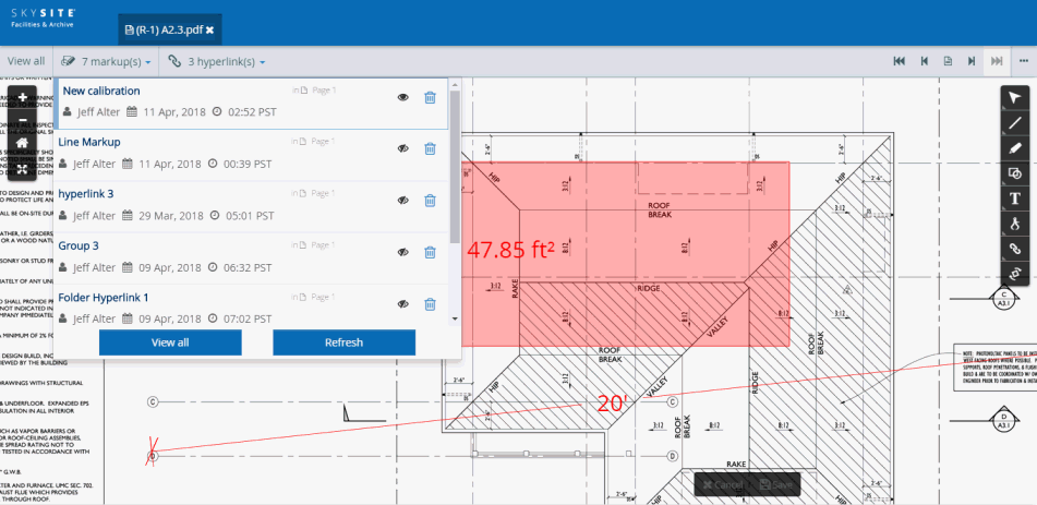
A drop-down appears which displays all the annotations which have been created and saved on this document (the current file). The newly saved calibration annotation is, by default, displayed on the document. Each row displays the name of the annotation, the name of the user who created the annotation and the number of annotations that have been saved (Count).
Click
 [Toggle
markup view ON/OFF] button
to make the calibration annotation disappear from the document, hence
becomes hidden from user view. This button changes to
[Toggle
markup view ON/OFF] button
to make the calibration annotation disappear from the document, hence
becomes hidden from user view. This button changes to  icon.
icon.
Click
button to make the calibration annotation
appear again on the document.
User can click the [View all] button to view all the annotations that had been saved on the document.
Scenario 1: Deletion of Calibration line will set Measurement values of all Measurement annotations to 0 (zero).
Scenario 2: Update of calibration line by dragging a loose end would simultaneously update all Measurement annotations present in document.
Scenario 3: If user clicks the [Create markup] button then the tool-bar reappears and the currently drawn and saved calibration annotation disappears from the document screen.
You can save multiple markups and hyperlinks together in a group. For example, 4 markups and 1 hyperlink is drawn and displayed on the Viewer screen. This is shown below,
Click [Save] button to save the markups and hyperlinks together.
The Save markup name as pop-up box appears. This pop-up box is shown below,
Enter the name of the markups & the hyperlink saved together as a group.
Click [Save] button to save the no. of drawn markups and the hyperlink as a group
After you save the markup group, it will appear under the 'Saved markup(s)' drop-down present on the top of the Viewer.
Click the 'Saved markup(s)' drop-down [highlighted with red rectangle on the screenshot below] to view all the saved markups drawn & saved previously on the document.
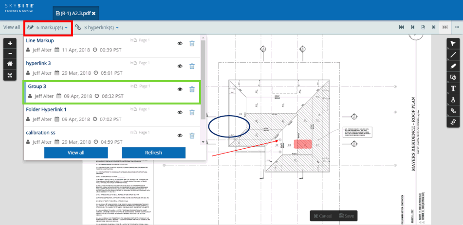
Now, click on the 'recently drawn & saved markup group' row [highlighted with green rectangle on the screenshot above] to make the markup annotation shape appear & disappear on the document.
Click
 [Delete] button to delete
the saved markup group.
[Delete] button to delete
the saved markup group.
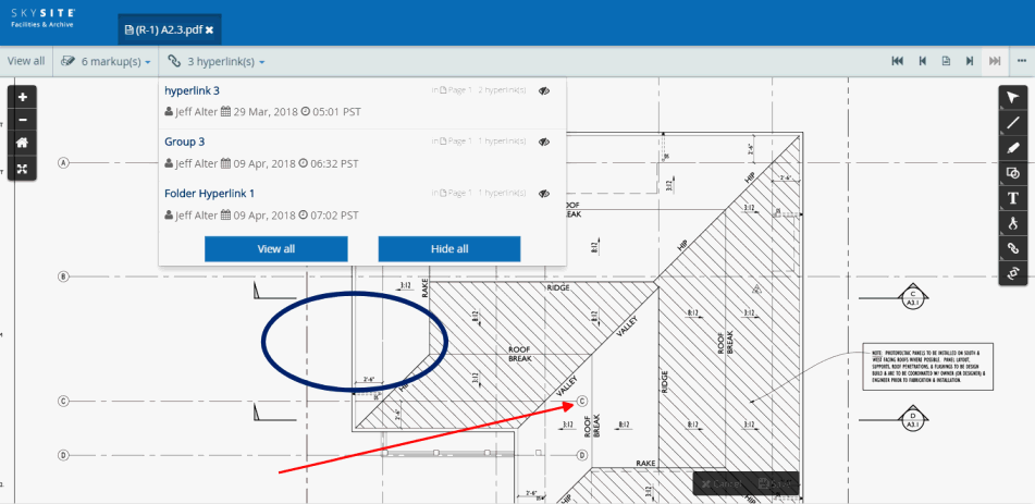
The hyperlink shape saved with the markup(s) in the group will appear under the 'Saved hyperlink(s)' drop-down. This is shown in screenshot below,
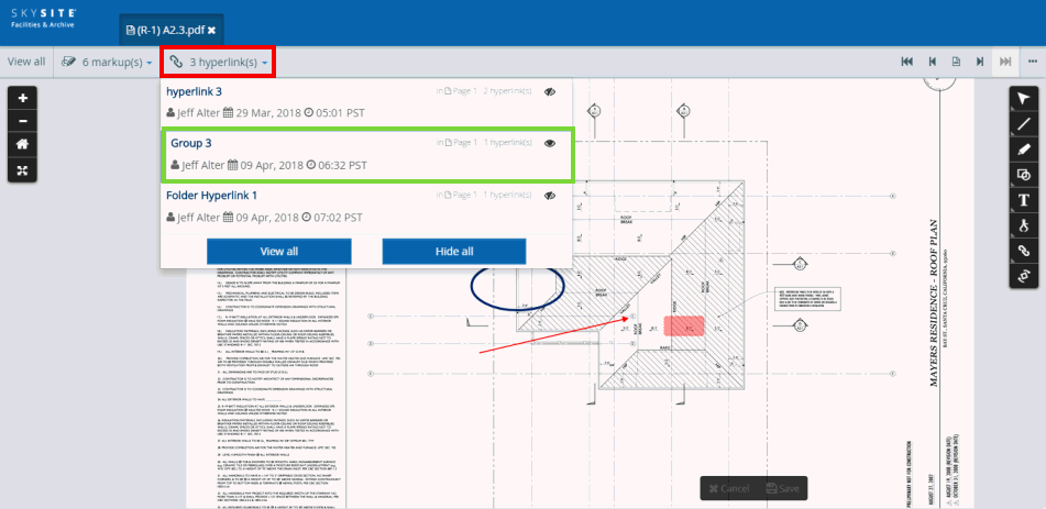
This icon [Toggle
markup view ON/OFF] on the 'Saved
markup(s)' drop-down means that the markup group shapes are visible
on the Viewer and this icon means that the markup
group shapes are hidden from view. You can click on the saved annotation
row to make the markup group shapes appear and disappear. The [Toggle
markup view ON/OFF] icon on the 'Saved
hyperlink(s)' drop-down (beside the saved markup group name) will
make only the saved hyperlink (saved as part of the group) appear and
disappear. This is shown in the screenshot below,
Note: After the markups are saved you cannot change the color, thickness, stretch the lines or move the line or for that matter do anything on the markups except make the markup appear & disappear from the Viewer screen. You can only delete the saved markup from the 'Saved markup(s)' drop-down.


 Draw
rectangular highlight
Draw
rectangular highlight


